Home/Machining Shop
Facility & equipment

The floor, in detail.

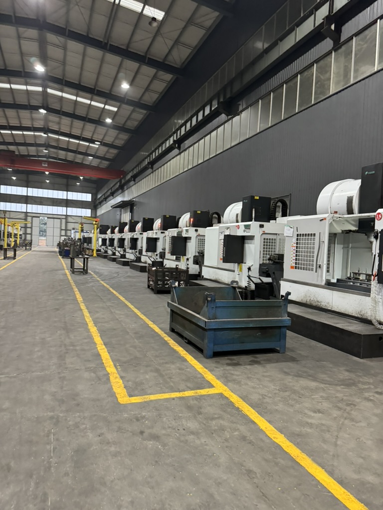
48 CNC machines, a metrology lab and finishing lines under one roof. Every machine listed below is production equipment — not a capability brochure.

Equipment list

Machines that do
the cutting.

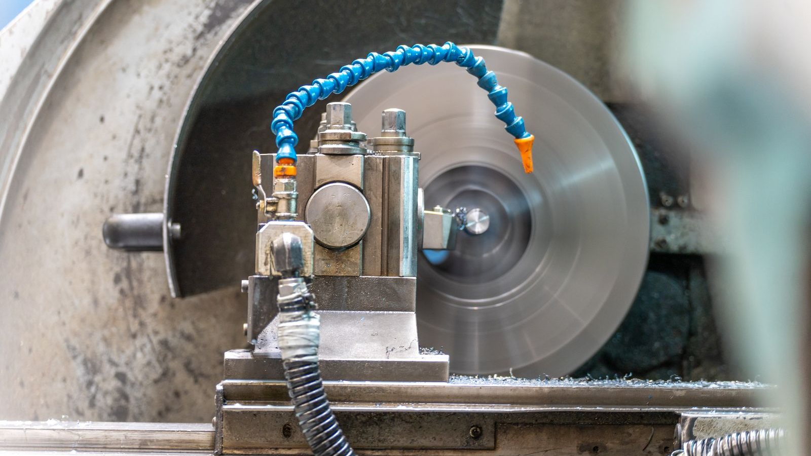
Representative shop-floor photography of the equipment families we run. Replace the files in assets/img/equipment/ with your own machine photos — file names are already wired up.
CNC turning centre in operation

CNC Turning Centre

8 UNITS · 2 WITH BAR FEEDER
  • Max turning diameterØ 420 mm
  • Max turning length800 mm
  • Spindle speed4,500 rpm
  • Positioning accuracy± 0.005 mm
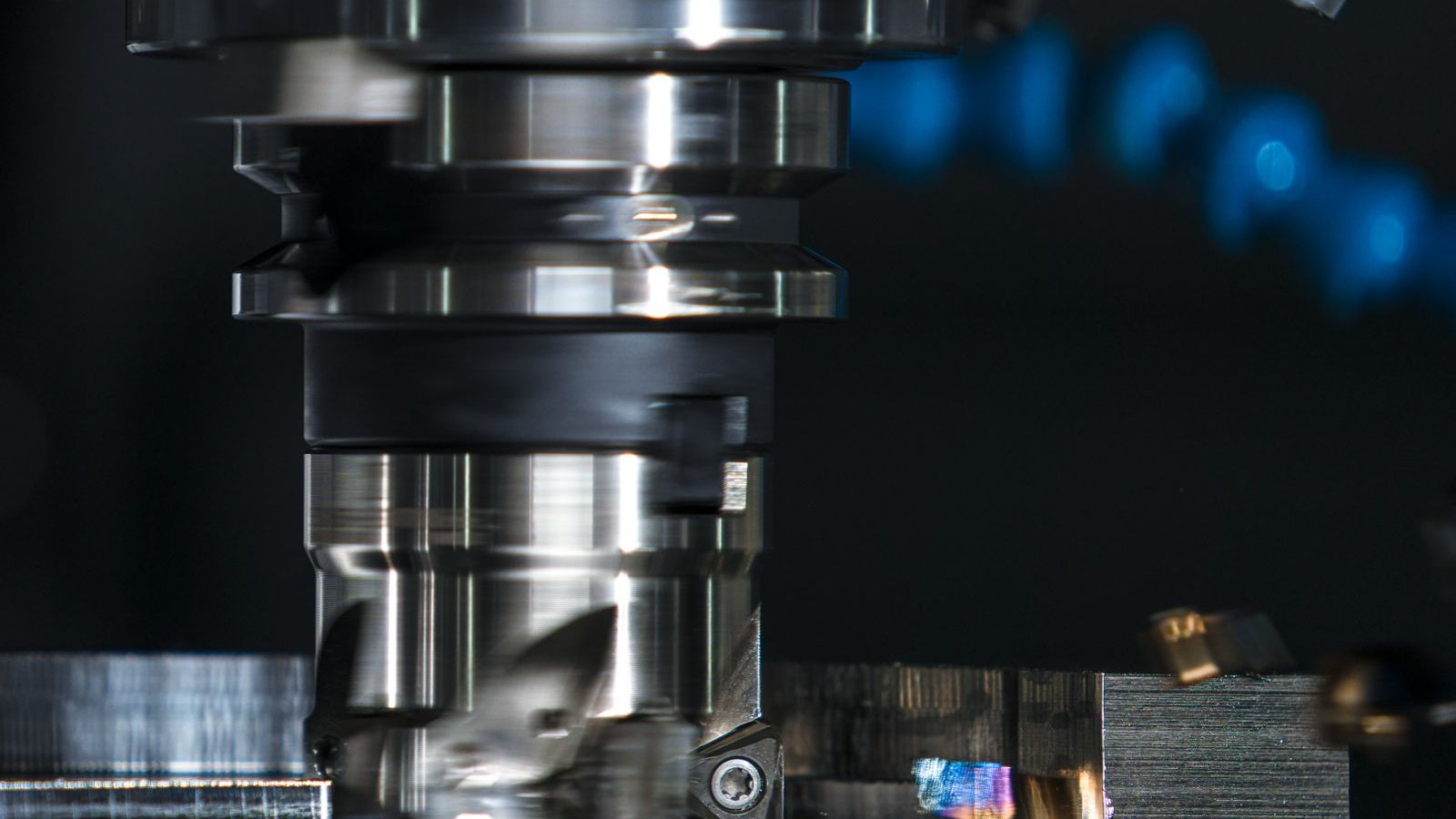
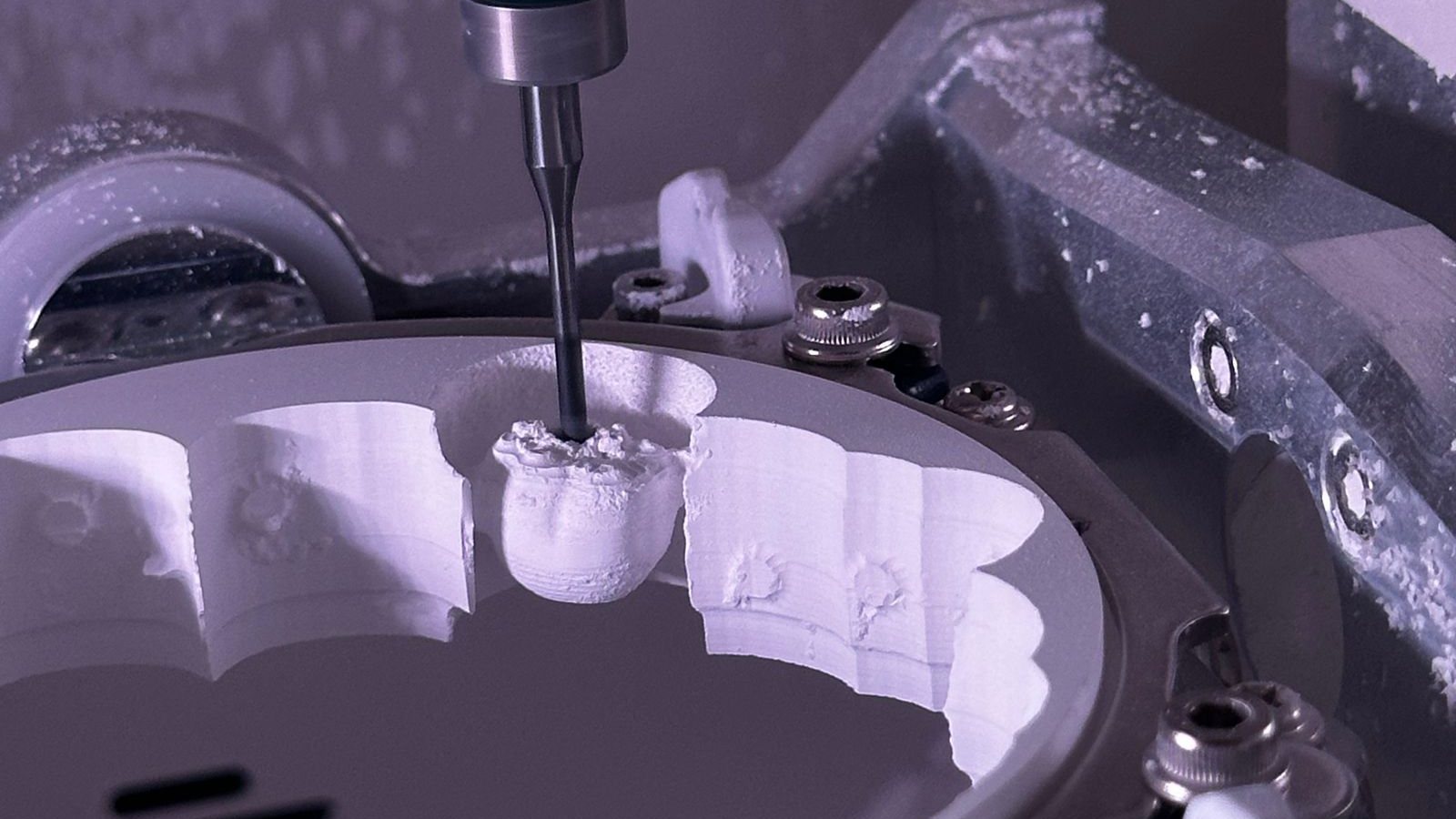
5-axis machining centre cutting a ring

5-Axis Machining Centre

4 UNITS · SIMULTANEOUS 5-AXIS
  • Travel (X / Y / Z)800 / 600 / 500 mm
  • Table load500 kg
  • Spindle18,000 rpm · HSK-A63
  • Positioning accuracy± 0.008 mm
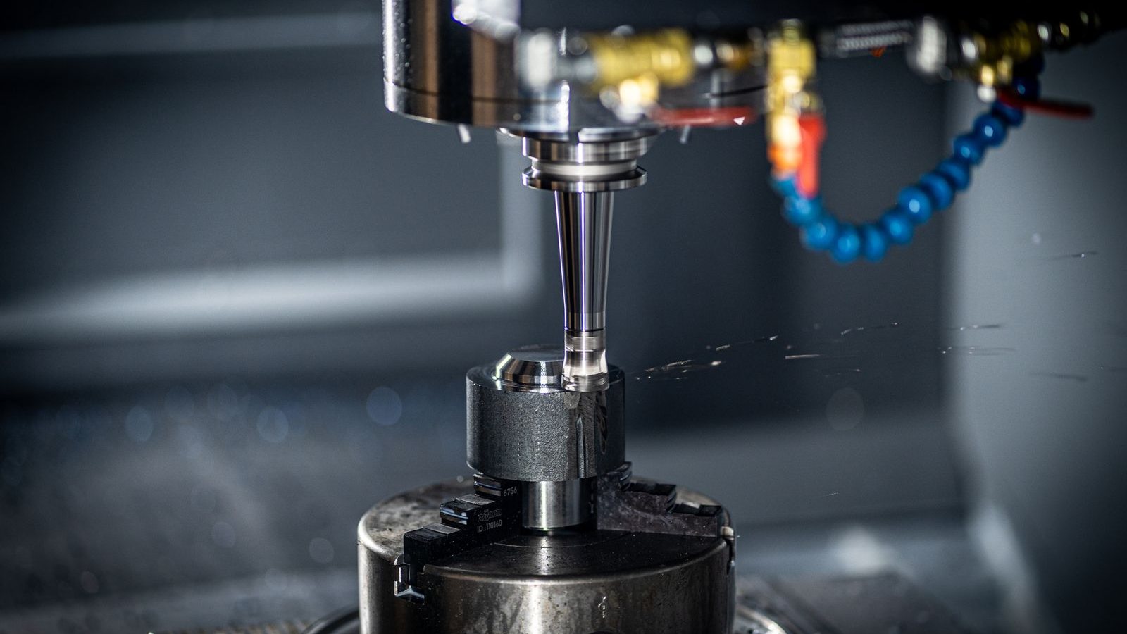
Vertical machining centre spindle

Vertical Machining Centre

12 UNITS · 3 WITH 4TH AXIS
  • Travel (X / Y / Z)1,100 / 600 / 600 mm
  • Tool stations24 ATC
  • Spindle speed10,000 rpm
  • Positioning accuracy± 0.008 mm
Horizontal boring and milling machine

Horizontal Boring & Milling

2 UNITS · LARGE ENVELOPE
  • Table size1,600 × 1,400 mm
  • Max workpiece weight6,000 kg
  • Boring diameterØ 10 – 400 mm
  • Positioning accuracy± 0.015 mm
CNC grinding operation with coolant

CNC Cylindrical Grinder

3 UNITS · EXTERNAL / INTERNAL
  • Grinding diameterØ 8 – 320 mm
  • Grinding length1,000 mm
  • Surface roughnessRa 0.2 µm
  • Roundness≤ 0.002 mm
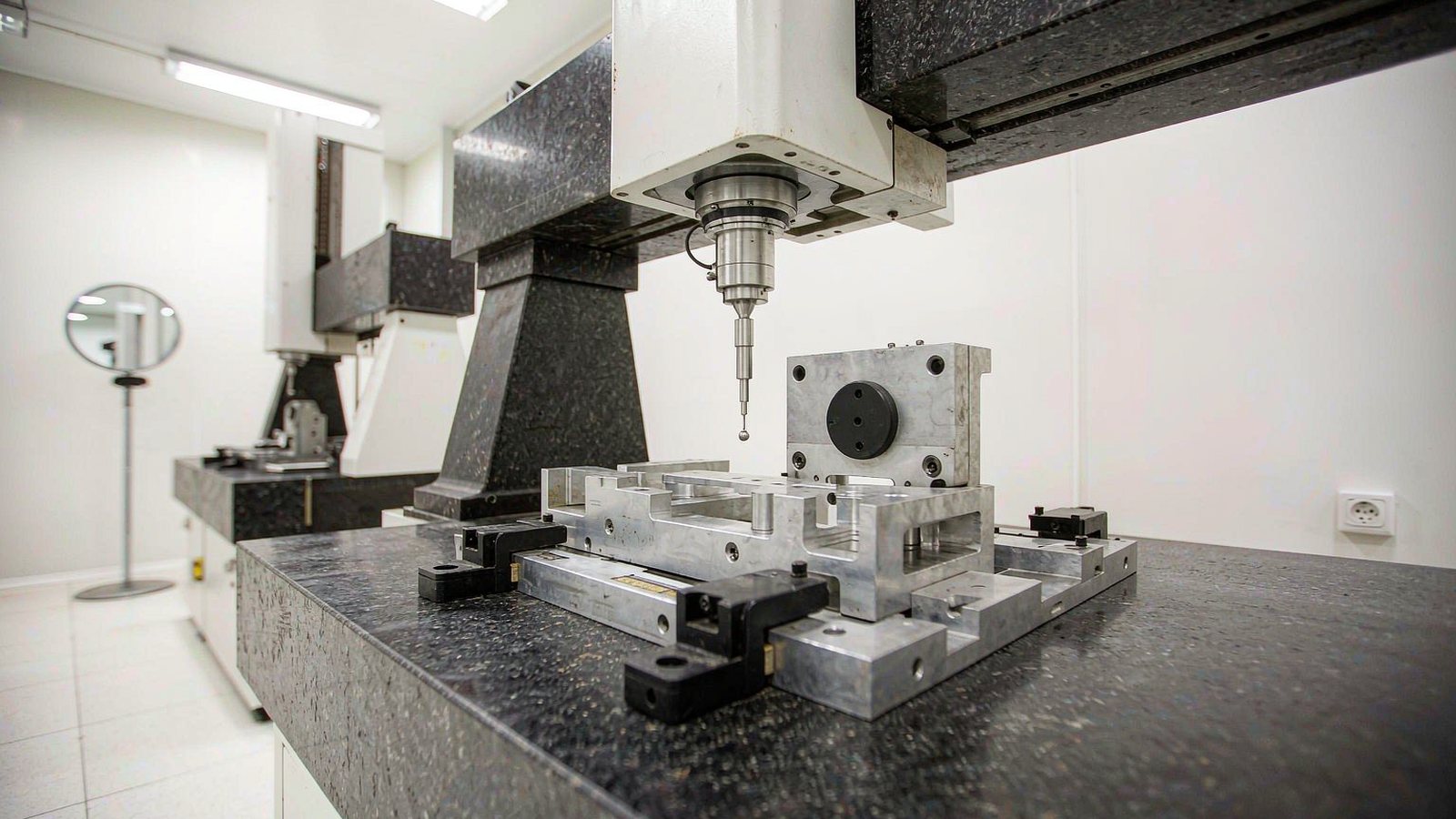
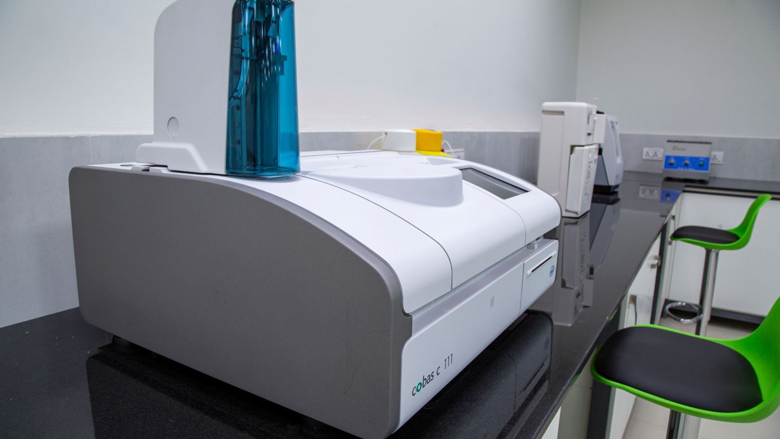
Coordinate measuring machine in the metrology lab

Coordinate Measuring Machine

2 UNITS · 20 ± 1 °C LAB
  • Measuring range1,200 × 900 × 700 mm
  • Volumetric accuracy2.2 + L/300 µm
  • Probe systemScanning, PH10T
  • OutputFirst article / PPAP report
Material testing and analysis equipment

Hardness & Material Testing

ROCKWELL · BRINELL · SPECTROMETER
  • Hardness scalesHRC / HBW / HV
  • Material analyserOptical emission
  • Coating thickness0 – 1,250 µm
  • TraceabilityHeat-lot linked
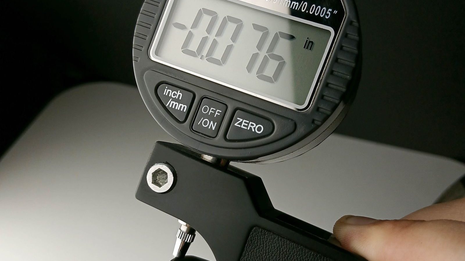
Digital micrometer measuring a machined surface

Surface & Geometry Checks

ROUGHNESS · PROFILE · OPTICAL
  • Roughness rangeRa 0.02 – 10 µm
  • Profile projectorØ 350 mm screen
  • Thread / gear checksPitch & profile gauges
  • ReportingPer-lot inspection sheet
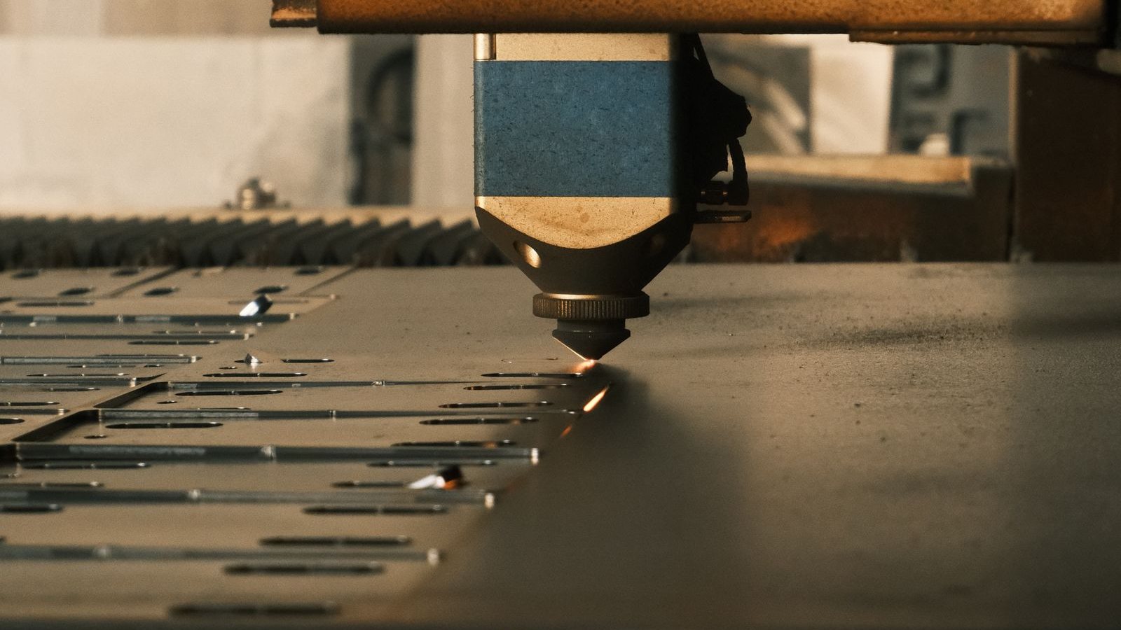
Fiber laser cutter cutting sheet metal

Fiber Laser Cutter

2 UNITS · 6 kW · AUTO NESTING
  • Cutting area3,000 × 1,500 mm
  • Material thickness0.5 – 20 mm
  • Positioning accuracy± 0.05 mm
  • MaterialsMild steel, SST, aluminum
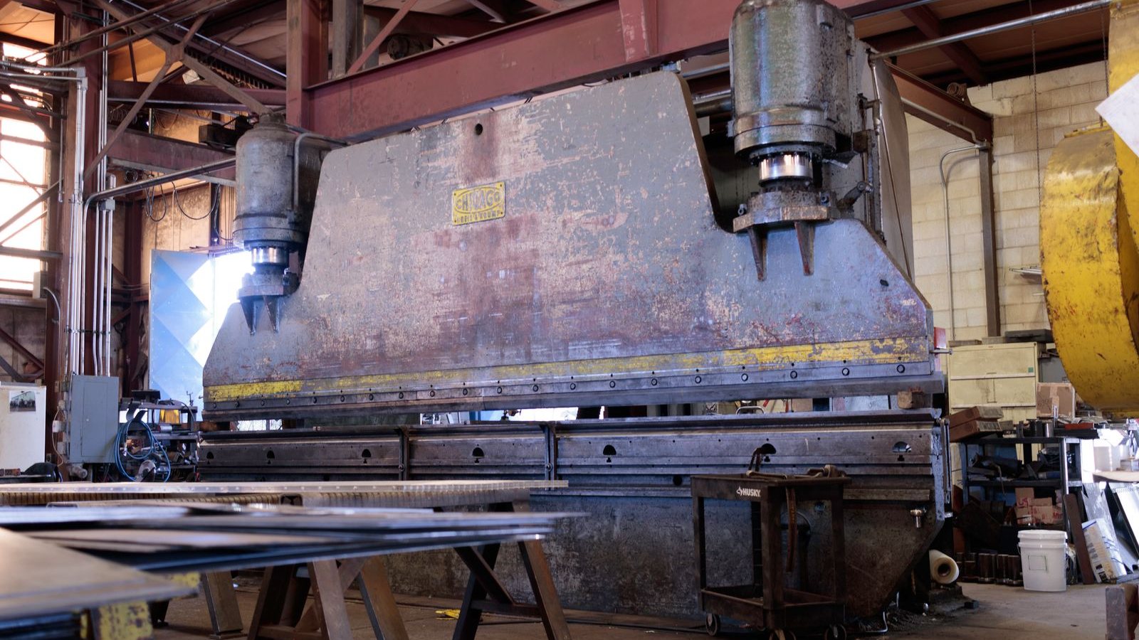
Press brake in the fabrication bay

Press Brake & Welding Bay

200 T · MIG / TIG / SPOT
  • Bending force200 t
  • Bending length3,200 mm
  • WeldingMIG, TIG, spot, robot cell
  • Post-processDeburr, powder coat
Quality control

Nothing ships
unmeasured.

Inspection is a gate, not a department. Each order passes three checkpoints before it reaches the packing bench.

StageWhat is checkedEquipmentRecord
Incoming material Heat-lot certificate, chemistry, hardness Spectrometer, hardness tester Material cert
First article All drawing dimensions, GD&T, surface finish CMM, roughness tester FAIR report
In-process Critical features every 10–20 pieces Micrometer, bore gauge, CMM SPC sheet
Final inspection AQL sampling, visual, thread and fit checks Gauges, profile projector Inspection sheet
Pre-shipment Quantity, labelling, packaging, documents Checklist Packing list
LAB / 01

20 ± 1 °C

Metrology room held at constant temperature so measurements mean something.

LAB / 02

Calibrated yearly

All gauges and instruments on a calibration schedule with external traceability.

LAB / 03

Reports in English

FAIR, PPAP and inspection reports issued in the format your QA team expects.

LAB / 04

5-year records

Inspection data archived by lot so a question in 2030 still has an answer.

Book a factory visit.

Audits, video walk-throughs and sample runs — tell us what your QA team needs to see.

Arrange a Visit